
Description
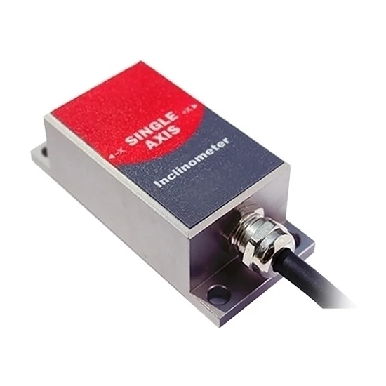
Cheap industrial inclinometer sensor features 1-axis/2-axis, Modbus output, output interface RS232, RS485, RS232, UART TTL, and optional measuring range±10°~±90°. It is an industrial tilt switch sensor with reliable, stable performance and good scalability, suitable for various harsh control environments.
Features
- The Modbus inclinometer sensor uses RS485 hardware differential bus to transmit data, single axis or dual axis is available.
- The tilt sensor has a built-in high-precision 16 bit A/D differential converter, which can measure the tilt and pitch angle of the sensor output relative to the horizontal plane through a 5-order filtering algorithm.
- Due to the built-in high-precision digital temperature sensor, the inclinometer sensor can correct the temperature drift according to the temperature value change, ensuring the high repeatability of the tilt sensor, in low and high temperature environments.
- The output response frequency standard of the inclinometer sensor can reach 18Hz. If you need a higher response frequency, you can contact us for customization.
Technical Specification
| Model | ATO-SCA116M-MB/SCA126M-MB | Condition | |||
| Measuring Axis | X/XY (single/dual) | X/XY (single/dual) | X/XY (single/dual) | X/XY (single/dual) | – |
| Measuring Range* | ±10° | ±30° | ±60° | ±90° | – |
| Resolution | 0.01° | 0.01° | 0.02° | 0.03° | – |
| Absolute Accuracy | 0.05° | 0.05° | 0.05° | 0.05° | @25℃ |
| Long Term Stability | 0.05° | 0.05° | 0.05° | 0.05° | – |
| Zero Temperature Coefficient | ±0.006°/℃ | ±0.006°/℃ | ±0.006°/℃ | ±0.006°/℃ | -40~85℃ |
| Sensitivity Temperature Coefficient | ≤100 ppm/℃ | ≤100 ppm/℃ | ≤100 ppm/℃ | ≤100 ppm/℃ | -40~85℃ |
| Power On Time | 0.5s | 0.5s | 0.5s | 0.5s | – |
| Response Time | 0.02s | 0.02s | 0.02s | 0.02s | – |
| Response Frequency | 5Hz, 15Hz, 35Hz, 50Hz for set | ||||
| Output Signal | Modbus | ||||
| Electromagnetic Compatibility | According to EN61000 and GBT17626 | ||||
| MTBF | ≥50000 hours/times | ||||
| Insulation Resistance | ≥100MΩ | ||||
| Shockproof | 100g@11ms, 3 Times/Axis (half sinusoid)) | ||||
| Anti-Vibration | 10grms, 10~1000Hz | ||||
| Protection Grade | IP67 | ||||
| High Seismic Performance | >2000g | ||||
| Cables | Standard 1m length, wearproof, grease proofing, wide temperature, shielded cables 4*0.4mm2 | ||||
| Dimension | 46*35.4*13.6mm | ||||
| Weight | 165g (without cable) |
*Note: This Technical data only list ±10°, ±30°, ±60°, ±90° series for reference, other measuring range please refer to the adjacent specifications.
Electrical Specification
| Item | Min | Standard | Max | Condition |
| Power Supply | 9V | 12V, 24V | 36V | Standard |
| – | 5V | – | Customizable | |
| Working Current | – | 42mA | – | 5V |
| – | 26mA | – | 12V | |
| – | 17mA | – | 24V | |
| Working Temperature | -40℃ | – | +85℃ | – |
| Store Temperature | -55℃ | – | +125℃ | – |
Modbus Inclinometer Sensor Electrical Wiring
- RS485 Wiring Definition
| Line Color Function | BLACK | WHITE | GREEN | RED |
| GND Power negative |
RS485 (D+) | RS485 (D-) | Vcc 9~36V Power positive |
- RS232/TTL Wiring Definition
| Line Color Function | BLACK | WHITE | GREEN | RED |
| GND Power negative |
RS232 (RXD) /TTL (RXD) |
RS232 (RXD) /TTL (RXD) |
Vcc 9~36V Power positive |
- RS422 Wiring Definition
| Line Color Function | RED | ORANGE | YELLOW | BLUE | PURPLE | BLACK |
| GND Power positive |
TXD+ | RXD- | RXD+ | TXD- | GND Power negative |
Modbus Inclinometer Sensor Dimensions Diagram
Inclinometer Sensor Installation Direction Diagram
The installation must guarantee the inclinometer sensor bottom is parallel to measured face,and reduce the influence of dynamic and acceleration to the tilt sensor. This inclinometer sensor can be installed horizontally or mounted vertically, for installation please refer to the following scheme.
Tips: Inclinometer sensor working principle.
Inclinometer sensor uses high-performance core control unit, using the principle of capacitive miniature pendulum. Inclinometer sensor uses the principle of earth’s gravity. When the inclination unit is tilted, the earth’s gravity will produce a component of gravity on the corresponding pendulum, and the corresponding capacitance will change. The inclination angle is obtained by amplifying, filtering, and converting the capacitance.
As shown in the figure, UL is the voltage between the left plate of the pendulum and its corresponding electrode, and UR is the voltage between the right plate and its corresponding electrode. When the inclinometer sensor is tilted, UL and UR will change according to a certain rule. Therefore, ξ (UL, UR) is a function of the inclination angle α: α = ξ (UL, UR)
Reviews
There are no reviews yet.